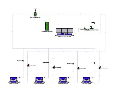
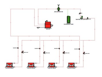
Chilled beams provide a very comfortable environment and deliver heating and cooling very efficiently. This is the case because most of the heating and cooling energy is delivered by a water hydronic pumping system, which is the most efficient way to move BTU’s. Cooling energy is generated by a chiller and cooling tower for water cooled systems. Heating energy is generated by a boiler. The system provides optimum comfort because the airflow within the conditioned space is a minimum. This reduces evaporative cooling on a person’s skin and provides better comfort. The reduced airflow also reduces air noise and provides a better environment. A passive chilled beam operates much like a radiant panel. Cold water circulates through a coil in a ceiling-mounted unit to provide radiant and natural convection cooling to the room below. Passive chilled beams are not used for heating since the heat transfer is only radiant. Any warm air from the coil will rise and not fall to the floor. An active chilled beam uses a radiant cooling coil but is also used to deliver dehumidified fresh air through slots along the sides of the chilled beam. The airflow across the coil substantially increases the (forced) convection and therefore cooling capacity of the air delivered to the room. The air is delivered at a temperature above the room dewpoint to prevent condensation. Active chilled beams can also provide heating. Both passive and active chilled beams are sensible cooling devices only since the air delivered is above the room dewpoint. A separate smaller ducted DOAS (direct outside air system) unit is used to provide dehumidification and ventilation. The DOAS unit typically brings in 100% fresh air in a large enough quantity to pressurize the building and prevent the infiltration of warm moist outside air. The DOAS airflow can be increased in those areas requiring fresh air ventilation for the occupants. This DOAS air is cooled and dehumidified to remove moisture that would come into the building through natural infiltration. This air can also be subcooled to remove internal humidity from people and processes.
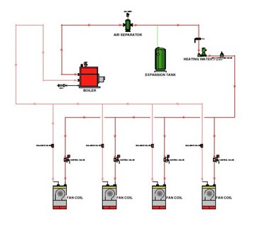
Fan-coil units are used as a local terminal unit to deliver heating, cooling and ventilation in one compact terminal unit. Heating and cooling energy is delivered by a water hydronic pumping system, which is the most efficient way to move BTU’s. Cooling energy is generated by a chiller and cooling tower for water cooled systems. Heating energy is generated by a boiler. The fan coil unit consists of an internal fan to force air across a hydronic or water coil and deliver treated air to the conditioned spaces. This reduces the cost of ductwork since a large central fan system is not required to move heating and cooling energy to each zone. Most fan coils use either a 3-speed motor or the newer ECM variable speed motor. This improves comfort since the unit can reduce airflow and reduce occupant skin evaporative cooling at less than design loads, which is the vast majority of the heating and cooling hours. The coil typically consists of multiple rows and can be sized to remove the entire humidity load in the space coming either from outside air or the occupants in the space. If the unit does full dehumidification the heating coil is placed downstream of the cooling coil to provide reheat. Reheat is necessary for good comfort if there is a low sensible load and high latent load from the room occupants. In this instance the air delivered must be subcooled to remove the latent load from the occupants. If the air is not reheated then the room will overcool and be uncomfortable. This is what creates the cold but clammy environment created by air units such as packaged rooftops and packaged terminal air conditioning or refrigeration units such as DX split systems or VRF. Reheat provides very comfortable conditions in high latent climates and something that the air and refrigerant systems cannot do. Fresh air for ventilation can be provided from a smaller ducted DOAS (direct outside air system) unit. The DOAS typically brings in 100% fresh air in smaller quantities for just the building occupants. This DOAS air can be cooled and dehumidified to remove moisture from the fresh air.
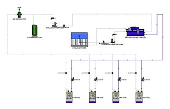
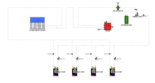
A water to air heat pump delivers heating, cooling and ventilation from one packaged unit. The unit consists of an internal fan to force air across a refrigerant coil to deliver treated air to the conditioned spaces. This reduces the cost of ductwork since a large central fan system is not required to move heating and cooling energy to each zone. Most fan coils use either a 2-speed motor or the newer ECM variable speed motor. This improves comfort since the unit can reduce airflow and reduce occupant skin evaporative cooling at less than design loads, which is the vast majority of the heating and cooling hours. A compressor moves refrigerant from the space conditioning coil to another internal refrigerant coil that either rejects heat or extracts heat from a central hydronic condenser water loop pumping system for the building. If the central condenser water loop heats up too much than the water is circulated through a closed-circuit cooler, similar to a cooling tower, that rejects the excess heat to ambient air. This water-cooled system is more efficient in the cooling mode than an air cooled system since it rejects heat to the wet bulb instead of the dry bulb temperature of the ambient air. One control algorithm that is used is “chasing the wet bulb.” In this control scheme the central. If the water loop cools down too much than a boiler adds heat to the loop to provide heat to the loop and ultimately to the occupants from the heat pumps in each zone. Fresh air for ventilation can be provided from a smaller ducted DOAS (direct outside air system) unit. The DOAS typically brings in 100% fresh air in smaller quantities for just the building occupants. This DOAS air can be cooled and dehumidified to remove moisture from the fresh air.
Variable Air Volume (VAV) is a type of heating, ventilating, and/or air-conditioning (HVAC) system. Unlike constant air volume (CAV) systems, which supply a constant airflow at a variable temperature, VAV systems vary the airflow at a constant temperature. The advantages of VAV systems over constant-volume systems include more precise temperature control, reduced compressor wear, lower energy consumption by system fans, less fan noise, and additional passive dehumidification. These VAV Air Handling systems are usually part of a chiller and boiler plant, which provide the chilled water and heating water.
The simplest VAV system incorporates one supply duct that, when in cooling mode, distributes supply air at a constant temperature of approximately 55 °F (13 °C). Because the supply air temperature is constant, the air flow rate must vary to meet the rising and falling heat gains or losses within the thermal zone served. Even a simple VAV system has several advantages over a CAV system. One is more precise temperature control. To meet a space cooling load, a CAV unit operates the fan and compressor at full capacity until the temperature drops to a specified limit, and then the compressor turns off. This on/off cycling causes the temperature to fluctuate above and below the temperature setpoint. In a single-zone VAV unit, the fan speed varies depending on the actual space temperature and the temperature setpoint, while the compressor modulates the refrigerant flow to maintain a constant supply air temperature. The result is more precise space temperature control. Another advantage is energy savings and reduced wear. VAV fan control, especially with modern electronic variable-speed drives, reduces the energy consumed by fans, which can be a substantial part of the total cooling energy requirements of a building. Modulating control of the compressor also reduces wear and delivers further energy savings. A final advantage is increased dehumidification. Because VAV air flow is reduced under part-load conditions, air is exposed to cooling coils for a longer time. More moisture condenses on the coils, dehumidifying the air. Thus, although a constant-volume and a single-zone VAV unit maintain the same room temperature, the VAV unit provides more passive dehumidification and more comfortable space conditions.
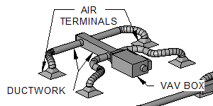
The air blower's flow rate is variable. For a single VAV air handler that serves multiple thermal zones, the flow rate to each zone must be varied as well. A VAV terminal unit, often called a VAV box, is the zone-level flow control device. It is basically a calibrated air damper with an automatic actuator. The VAV terminal unit is connected to either a local or a central control system. Historically, pneumatic control was commonplace, but electronic direct digital control systems are popular especially for mid- to large-size applications. Hybrid control, for example having pneumatic actuators with digital data collection, is popular as well.
A common commercial application is shown in the diagram. This VAV system consists of a VAV box, ductwork, and four air terminals.
Constant Air Volume (CAV) is a type of heating, ventilating, and air-conditioning (HVAC) system. In a simple CAV system, the supply air flow rate is constant, but the supply air temperature is varied to meet the thermal loads of a space. In mid- to large-size buildings, new central CAV systems are somewhat rare. Due to fan energy savings potential, variable air volume (VAV) systems are more common. However, in small buildings and residences, CAV systems are often the system of choice due to their simplicity, low cost, and reliability. Such small CAV systems often have on/off control, rather than supply air temperature modulation, to vary their heating or cooling capacities. There are two types of CAV systems that are commonly in use to modify the supply air temperature: the terminal reheat system and the mixed air system (which is no longer allowed under the new energy code). The terminal reheat system cools the air in the air handling unit down to the lowest possible needed temperature within its zone of spaces. This supplies a comfortable quality to the space, but wastes energy.
A geothermal heat pump or ground source heat pump (GSHP) is a central heating and/or cooling system that transfers heat to or from the ground. It uses the earth as a heat source (in the winter) or a heat sink (in the summer). This design takes advantage of the moderate temperatures in the ground to boost efficiency and reduce the operational costs of heating and cooling systems, and may be combined with solar heating to form a geosolar system with even greater efficiency. They are also known by other names, including geoexchange, earth-coupled, earth energy systems. The engineering and scientific communities prefer the terms "geoexchange" or "ground source heat pumps" to avoid confusion with traditional geothermal power, which uses a high temperature heat source to generate electricity. Ground source heat pumps harvest heat absorbed at the Earth's surface from solar energy. The temperature in the ground below 6 meters (20 ft) is roughly equal to the mean annual air temperature at that latitude at the surface. Depending on latitude, the temperature beneath the upper 6 meters (20 ft) of Earth's surface maintains a nearly constant temperature between 10 and 16 °C (50 and 60 °F), if the temperature is undisturbed by the presence of a heat pump. Like a refrigerator or air conditioner, these systems use a heat pump to force the transfer of heat from the ground. Heat pumps can transfer heat from a cool space to a warm space, against the natural direction of flow, or they can enhance the natural flow of heat from a warm area to a cool one. The core of the heat pump is a loop of refrigerant pumped through a vapor-compression refrigeration cycle that moves heat. Air-source heat pumps are typically more efficient at heating than pure electric heaters, even when extracting heat from cold winter air, although efficiencies begin dropping significantly as outside air temperatures drop below 5 °C (41 °F).[citation needed] A ground source heat pump exchanges heat with the ground. This is much more energy-efficient because underground temperatures are more stable than air temperatures through the year. Seasonal variations drop off with depth and disappear below 7 meters (23 ft) to 12 meters (39 ft) due to thermal inertia. Like a cave, the shallow ground temperature is warmer than the air above during the winter and cooler than the air in the summer. A ground source heat pump extracts ground heat in the winter (for heating) and transfers heat back into the ground in the summer (for cooling). Some systems are designed to operate in one mode only, heating or cooling, depending on climate. Geothermal pump systems reach fairly high coefficient of performance (CoP), 3 to 6, on the coldest of winter nights, compared to 1.75–2.5 for air-source heat pumps on cool days. Ground source heat pumps (GSHPs) are among the most energy efficient technologies for providing HVAC and water heating. Setup costs are higher than for conventional systems, but the difference is usually returned in energy savings in 3 to 10 years, and even shorter lengths of time with federal, state and utility tax credits and incentives. Geothermal heat pump systems are reasonably warranted by manufacturers, and their working life is estimated at 25 years for inside components and 50+ years for the ground loop. As of 2004, there are over one million units installed worldwide providing 12 GW of thermal capacity, with an annual growth rate of 10%.
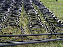
Heat pumps provide winter heating by extracting heat from a source and transferring it into a building. Heat can be extracted from any source, no matter how cold, but a warmer source allows higher efficiency. A ground source heat pump uses the top layer of the earth's crust as a source of heat, thus taking advantage of its seasonally moderated temperature. In the summer, the process can be reversed so the heat pump extracts heat from the building and transfers it to the ground. Transferring heat to a cooler space takes less energy, so the cooling efficiency of the heat pump gains benefits from the lower ground temperature. Ground source heat pumps employ a heat exchanger in contact with the ground or groundwater to extract or dissipate heat. This component accounts for anywhere from a fifth to half of the total system cost, and would be the most cumbersome part to repair or replace. Correctly sizing this component is necessary to assure long-term performance: the energy efficiency of the system improves with roughly 4% for every degree Celsius that is won through correct sizing, and the underground temperature balance must be maintained through proper design of the whole system. Incorrect design can result in the system freezing after a number of years or very inefficient system performance; thus accurate system design is critical to a successful system. Shallow 3–8-foot (0.91–2.44 m) horizontal heat exchangers experience seasonal temperature cycles due to solar gains and transmission losses to ambient air at ground level. These temperature cycles lag behind the seasons because of thermal inertia, so the heat exchanger will harvest heat deposited by the sun several months earlier, while being weighed down in late winter and spring, due to accumulated winter cold. Deep vertical systems 100–500 feet (30–152 m) deep rely on migration of heat from surrounding geology, unless they are recharged annually by solar recharge of the ground or exhaust heat from air conditioning systems. Several major design options are available for these, which are classified by fluid and layout. Direct exchange systems circulate refrigerant underground, closed loop systems use a mixture of anti-freeze and water, and open loop systems use natural groundwater. Ground Heat Exchangers are available in several types: Direct Exchange Closed Loop, both Vertical & Horizontal Radial or Directional Drilling Pond Open Loop Standing Column Well
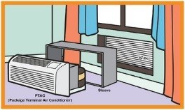
PTAC stands for "packaged terminal air conditioner." PTACs are single, commercial grade, self-contained units installed through a wall and often found in hotels. A PTAC's compressor system both cools and heats. To cool, the units compressor pumps refrigerant to cool the coils which attracts heat and humidity which is then exhausted to the outside. To heat, this functionality is reversed. The refrigerant is used to heat the coils, and when air passes over it the unit pushes the heated air into the room. PTACs are larger than a typical through-the-wall air conditioner; the standard size is 42" wide. PTACs are often seen in the hospitality industry and are approved for commercial use, but they are also suitable for residential applications.
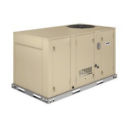
In a typical rooftop unit, the compressor is located at one end of the cabinet and condenser coils are wrapped around or in close proximity to it. Cool, low-pressure refrigerant arrives at the compressor as a gas. It compresses into a hot, high-pressure gas as it flows into the condenser coil, where it gives off its heat. The metal fins on the coil act as a heat sync and the condenser fan blows the exhaust up and away from the building. Warm return air travels through the ductwork into the rooftop unit, and fresh air enters as well for ventilation purposes. Air filters are positioned over the return air duct and fresh air intake to trap contaminants and prevent them from landing on the sensitive cooling equipment. Returning to the refrigerant cycle, the now-cooled liquid refrigerant passes through the evaporator coil. The pressure drops, and as the liquid evaporates, it converts back into a gas. As warm air from inside the building passes over the evaporator coil, the refrigerant extracts heat from the air, making it ice-cold when the evaporator fan blows it back into the building. Upon leaving the evaporator coil, the refrigerant is warm, having absorbed heat from the return air. It circulates back to the compressor to give off its heat, and the cycle begins all over again. This process repeats continuously until the temperature in your building reaches the thermostat setting. Rooftop units that also provide heating often contain a gas heat exchanger downstream from the evaporator fan. In heating mode, return air is discharged into the heater and blows over gas-fired coils. A fan then sends newly heated supply air back into the building.
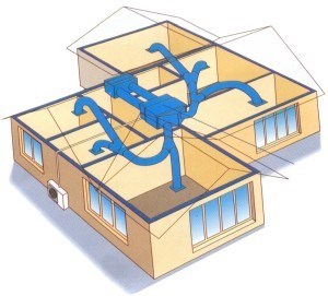
A split air conditioner consists of two main parts: the outdoor unit and the indoor unit. The outdoor unit is installed on or near the wall outside of the room or space that you wish to cool. The unit houses the compressor, condenser coil and the expansion coil or capillary tubing. The sleek-looking indoor unit contains the cooling coil, a long blower and an air filter. A split air conditioner does not require major installation work because it does not require ductwork. Rather, the indoor and outdoor units are connected with a set of electrical wires and tubing. This is good for your wallet and the environment. The ductwork required for many traditional A/C units generally increases energy expenditures, as many centralized A/C units lose a lot of energy due to heat exchange in the air duct system. So, without a duct system, there is very little opportunity for heat or energy loss in a split air conditioner system. This kind of air conditioner system has many advantages over traditional air conditioners. Perhaps the most obvious benefit is the quiet performance of a split air conditioner system. The parts of an air conditioner that make the most noise are the compressor and the fan that cools the condenser. In a split system, the compressor and fan for the condenser are located outside of the room being cooled and therefore the major sources of noise are removed - unlike with window units. Another benefit of a split air conditioner system is that you can opt for a multi-split system, where you can have more than one indoor unit connected to a single outdoor unit. This makes it easy to cool multiple rooms or maintain the temperature throughout a large room through the use of two indoor cooling units. A split air conditioner is an efficient and cost-effective way to cool your home. It should be noted that the initial cost of this kind of air conditioning unit is significantly higher than a window unit and it does require professional installation. However, the amount of money you will save on your energy bills as well as the longevity of the unit will make it worth your while in the end.
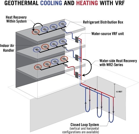
Variable refrigerant flow (VRF) zoning and geothermal systems are two options for heating and cooling buildings. Now, the benefits of both systems can be combined. This article provides an overview of geothermal (or water-source) with VRF zoning technology, and its advantages compared to traditional geothermal systems, air-source VRF zoning systems, and conventional HVAC systems. Additionally, the article discusses considerations for specifying water-source VRF zoning systems and provides case studies of successful applications. VRF zoning provides precise comfort control to buildings with multiple floors and areas by moving refrigerant through piping to the zone to be cooled or heated. Some VRF zoning systems offer highly responsive simultaneous cooling and heating, which maximizes use of heat energy that otherwise would be expelled outdoors. Regardless of the time of day, sun or shade, season, or special requirements, VRF zoning systems can deliver comfort tailored to each zone or space. Outdoor temperatures fluctuate with the changing seasons, but underground temperatures do not change as dramatically because of the earth’s insulating properties. Geothermal systems typically consist of heat exchange equipment located indoors, and a buried system of pipes—called ‘loops’—to capitalize on constant underground temperatures to provide energy. Water in the heat exchanger circulates through loops below the surface, absorbing or expelling heat to the below-ground heat sink depending on the time of year. This function ultimately reduces the load on the compressor during the cooling and heating cycles, and results in significant energy savings. Water-source VRF zoning systems combine a geothermal system’s benefits, with the sophistication of VRF zoning. Together, the technologies take advantage of the inverter-driven compressor coupled with a closed geothermal loop instead of air as a heat exchange medium. Water-source VRF zoning systems have numerous benefits, including many that users have come to expect from air-source VRF zoning systems. Flexible Installation Installation is possible in tight spaces because two-pipe designs require less space than ducted systems. Some VRF zoning systems require three- or four-pipe designs, which call for more refrigerant line runs and more brazed connections. Two-pipe designs minimize the total distance of refrigerant line and system connections, which can help reduce installation labor and eventual maintenance costs. Relatively small water-source VRF zoning condenser units are mounted indoors and can be installed in compact utility closets with minimal access on either side of the unit. Refrigerant, water, and electrical connections are housed on the front of the unit for convenient access. Application Variety Outdoor water-source VRF zoning units can be connected to an array of indoor unit styles to accommodate the space’s specific needs. All styles are quiet, easy to maintain, and provide optimal comfort. The configuration of the below-ground loop systems can be customized to accommodate the building’s surroundings. For example, loops can be buried under a building or a parking lot by drilling either vertical bore holes or horizontal trenches.